← Back to portfolio

ANSYS Mechanical · Structural FEA · Reactor-internals-inspired screening · Python reporting

Structural FEA Reactor Internals Pilot Study

Educational ANSYS Mechanical pilot study for a simplified reactor-internals-inspired stainless-steel support plate, framed for structural-analysis roles that need careful FEM setup, load-case traceability, result interpretation, thermal-support judgement and clear engineering reports.

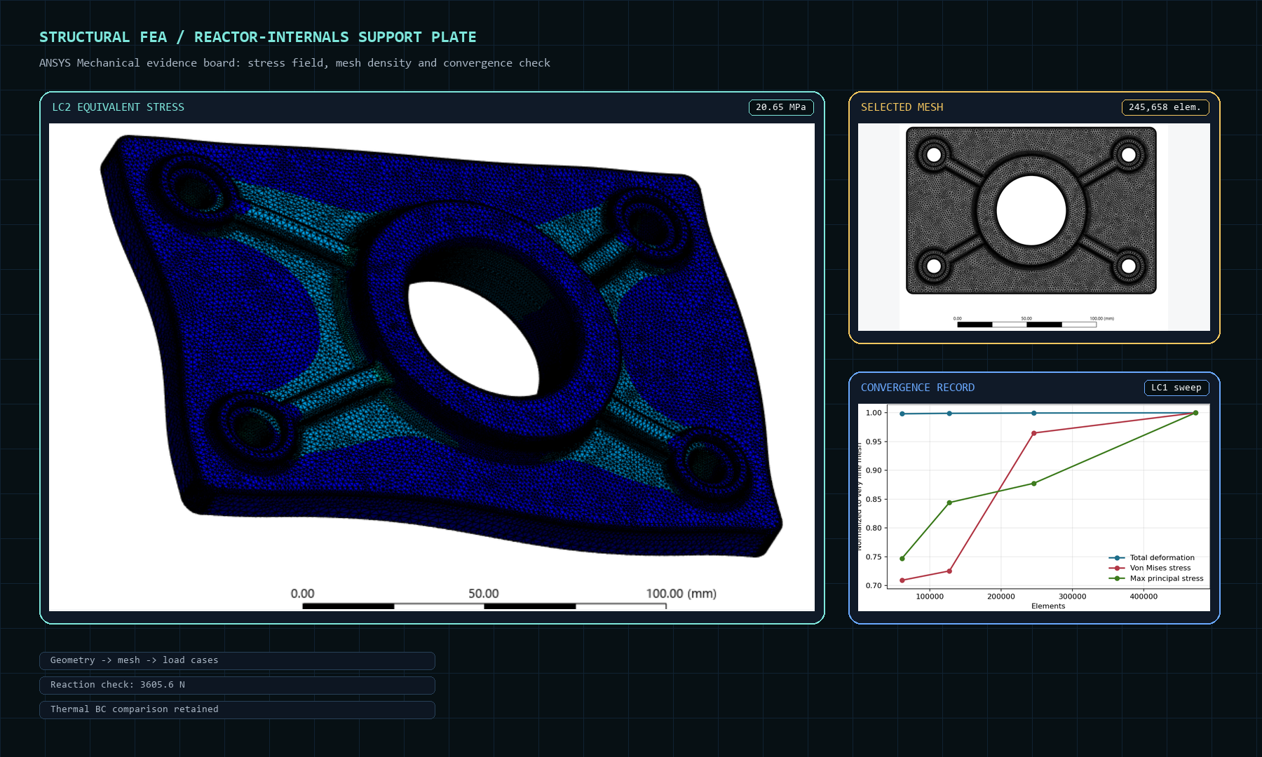
Designed structural FEA evidence board showing LC2 stress, selected mesh and convergence plot
Curated web figure assembled from ANSYS Mechanical and Python outputs; original exports remain preserved as source evidence.

What this demonstrates for the role

For a Structural Analysis Engineer context, the evidence is not just the contour plot. It shows how I freeze assumptions, define load cases, run mesh convergence, check reaction forces, compare boundary-condition realism and post-process results reproducibly before writing the interpretation.

245,658 elementsFine mesh selected for final reporting 20.65 MPaPeak von Mises in the 5 kN lateral case 3605.6 NLC3 reaction resultant from ANSYS, matching the applied vector resultant 0.0171 MPaLC4R thermal stress after expansion was allowed
ANSYS evidence views

Real screenshots from the FEA workflow

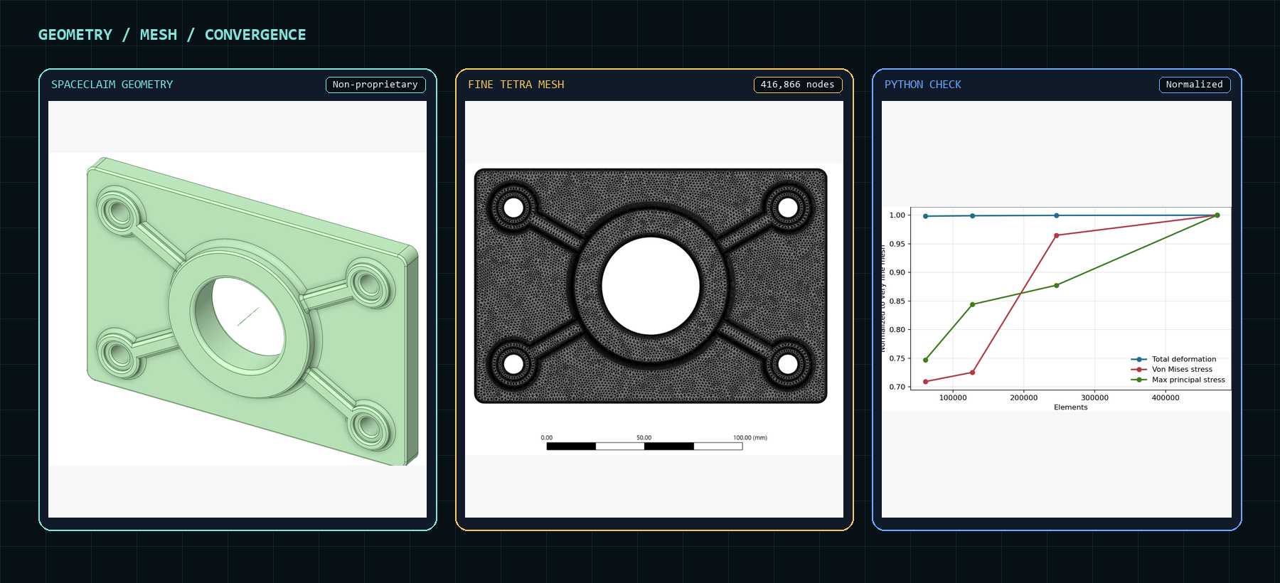
Curated structural FEA method board showing geometry, selected mesh and LC1 convergence plot
01 / Method evidence boardGeometry, reporting mesh and convergence are grouped into one figure so the analysis setup reads as a workflow rather than unrelated screenshots.
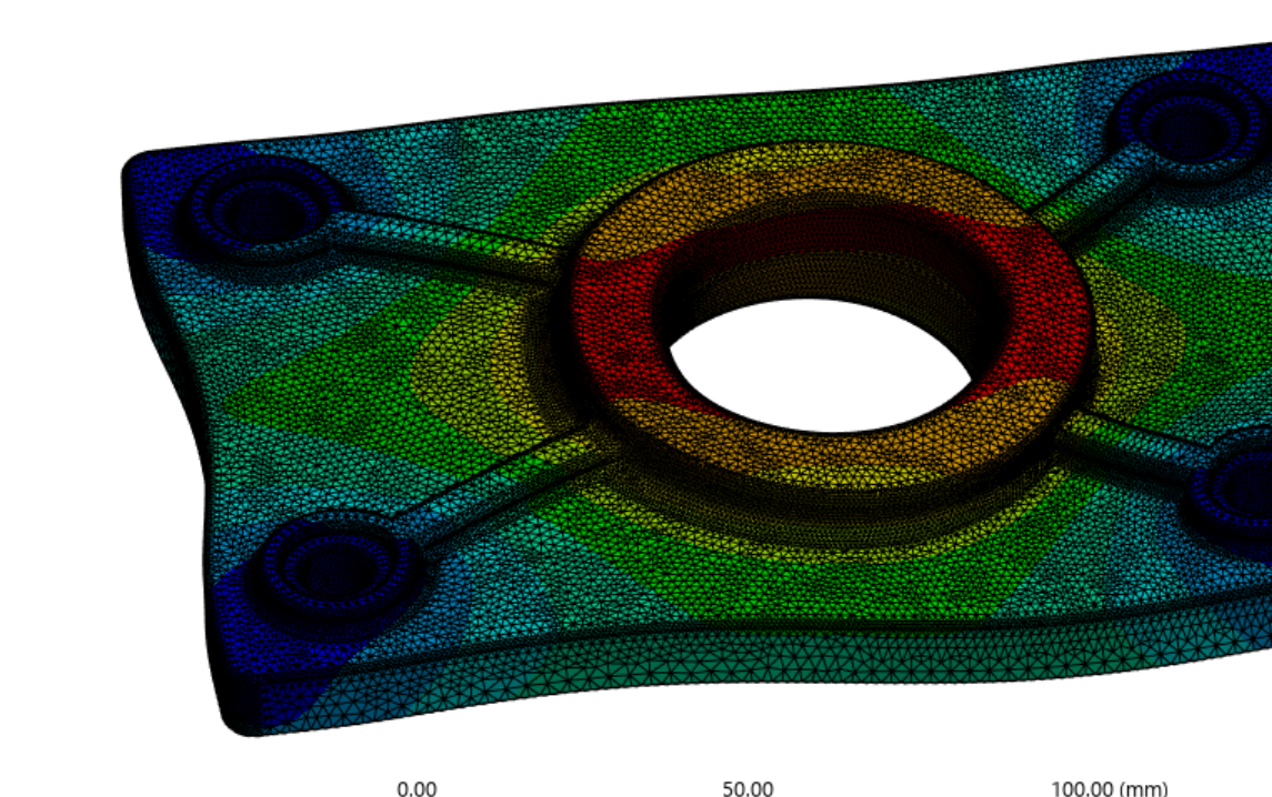
Cropped ANSYS LC1 total deformation field for the fine mesh
02 / LC1 deformation responseCropped to the plate response and scale bar; baseline mechanical case used for mesh sensitivity and stiffness scale.
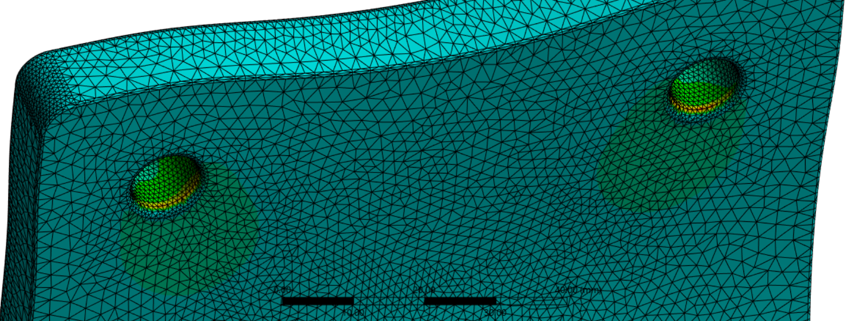
Cropped ANSYS LC1 backside mounting-hole hotspot detail screenshot
03 / Hotspot inspectionBackside mounting-hole view isolates the local stress concentration instead of showing the full ANSYS workspace.
Cropped ANSYS LC2 equivalent von Mises stress result under 5 kN lateral load
04 / LC2 stress field5 kN lateral screening case with 20.65 MPa peak von Mises stress and a preliminary factor of safety of 9.93 against the 205 MPa screening yield.
Cropped ANSYS LC3 reaction-force check for combined 3 kN lateral and 2 kN vertical loading
05 / Reaction-force checkLC3 resultant is 3605.6 N in ANSYS versus sqrt(3000^2 + 2000^2) = 3605.5 N, showing the model balances the applied vector load.

Boundary-condition judgment

LC4 is a warning; LC4R is the sanity check

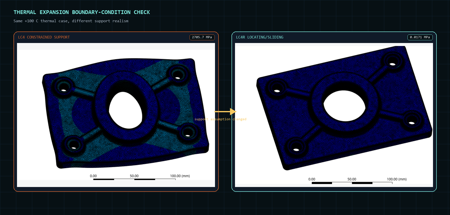
The thermal comparison is intentionally shown as a pair. Keeping fixed mounting holes during +100 C expansion creates an over-constrained artifact, while the locating/sliding support in LC4R allows thermal growth without artificial restraint.

Curated comparison board showing constrained LC4 thermal stress beside relaxed LC4R thermal stress
06 / Thermal support realismLC4 is kept as an over-constrained warning; LC4R is the accepted thermal sanity check with locating/sliding support.

Boundary-condition judgment

LC4 is a warning; LC4R is the sanity check

The thermal comparison is intentionally shown as a pair. Keeping fixed mounting holes during +100 C expansion creates an over-constrained artifact, while the locating/sliding support in LC4R allows thermal growth without artificial restraint.

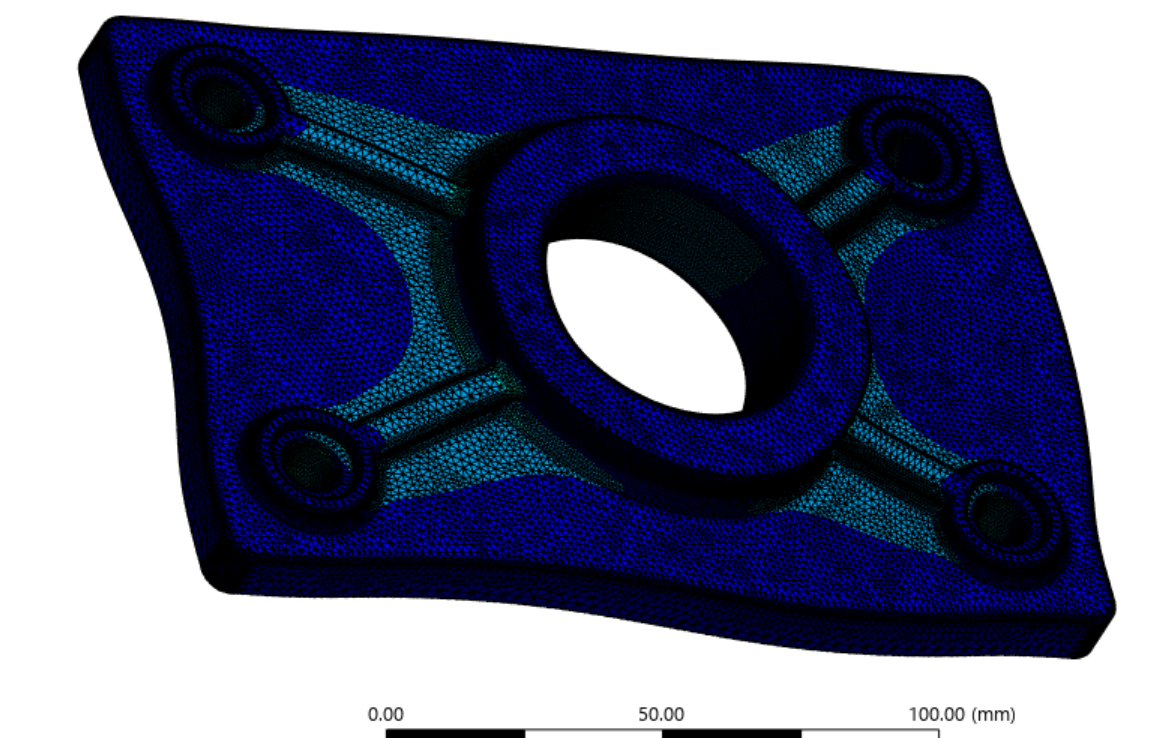
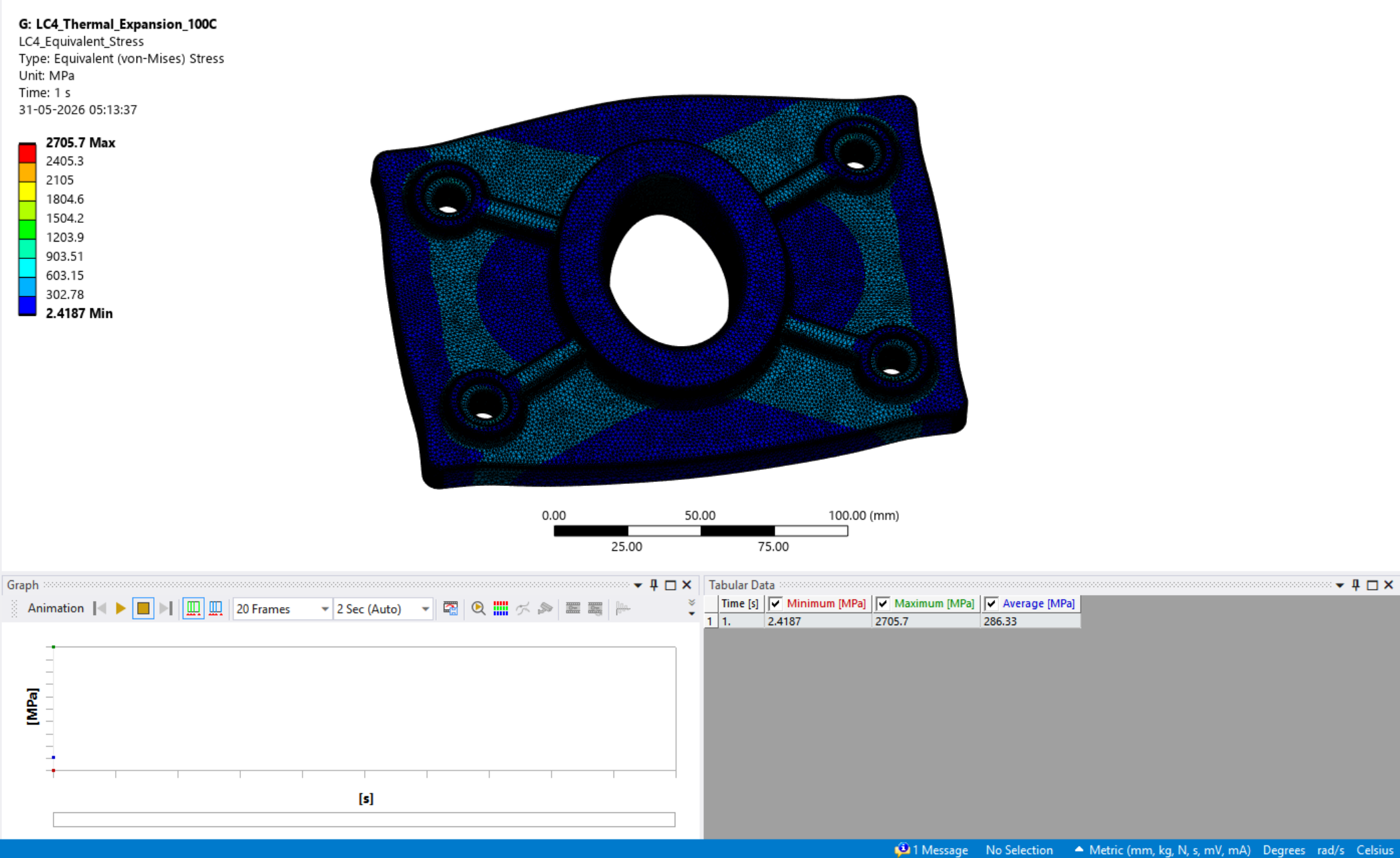
ANSYS constrained thermal expansion equivalent stress result showing over-constrained artifact stress
Over-constrained thermal caseRetained as a boundary-condition artifact warning, not as a design stress. The contour is useful because it shows what wrong support realism can do.
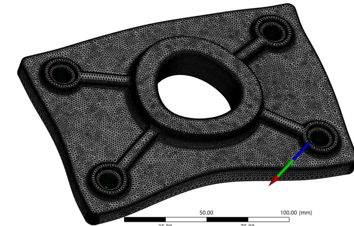
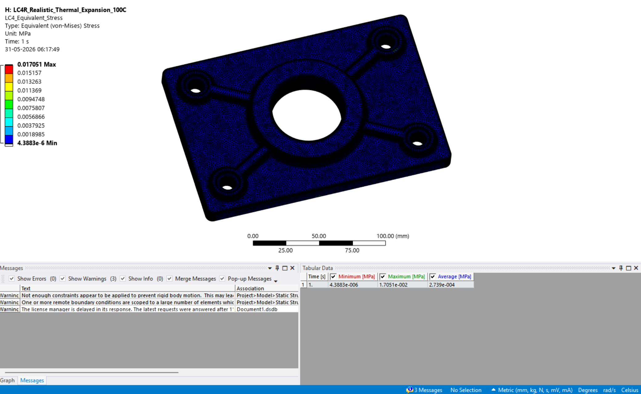
ANSYS relaxed thermal expansion equivalent stress result after changing the support condition
Relaxed thermal caseLocating/sliding support assumption allows expansion while preventing rigid-body motion; reported equivalent stress drops to 0.0171 MPa.

Method

Simulation workflow

  1. Geometry and material: built a non-proprietary stainless-steel support plate and used a linear-elastic annealed 316 stainless-steel material assumption.
  2. Boundary conditions: compared fixed mounting-hole supports for mechanical cases with a relaxed 3-2-1 locating/sliding support for realistic thermal expansion.
  3. Mesh convergence: ran LC1 across coarse, medium, fine and very-fine tetrahedral meshes; final fine mesh used 416,866 nodes and 245,658 elements.
  4. Verification: checked reaction forces against the applied loads, including LC3 resultant reaction: sqrt(3000^2 + 2000^2) = 3605.5 N versus 3605.6 N from ANSYS.
  5. Thermal solve gate: accepted LC4R only after solver results displayed normally, remote reactions stayed negligible and pivot, missing-result-file or disconnected-attachment states were removed.
  6. Post-processing: exported result CSVs and generated summary tables, figures and reporting values with Python.

Acceptance criteria

What the final report checked before freezing the model

The project uses an ASME-aware screening mindset without claiming formal ASME BPVC compliance. The repository now records the checks as an explicit acceptance matrix, so the analysis reads as an engineering workflow rather than an isolated contour-plot gallery.

Quantity Criterion How checked
Max von Mises stress Below preliminary yield-strength screen Compared with 205 MPa assumed yield strength for annealed 316 stainless steel.
Max deformation Small relative to component size and support function Reviewed displacement magnitude and deformation pattern for each load case.
Reaction force Balance applied mechanical load Compared ANSYS reaction resultants with LC1, LC2 and LC3 applied load resultants.
Mesh convergence Stable final mesh response Used the LC1 coarse, medium, fine and very-fine mesh convergence study.
Thermal stress Interpreted through support realism Compared fixed-hole LC4 with relaxed 3-2-1 LC4R before accepting the thermal case.

Results

Final load-case interpretation

Case Max deformation Max von Mises Interpretation
LC1 - 2 kN lateral 0.000366 mm 8.26 MPa Baseline mechanical load; reaction balanced at 2000 N.
LC2 - 5 kN lateral 0.000915 mm 20.65 MPa Linear scaling case; preliminary factor of safety 9.93 against 205 MPa screening yield.
LC3 - combined load 0.001009 mm 19.572 MPa Combined 3 kN lateral + 2 kN vertical; reaction resultant check passed.
LC4 - constrained thermal 0.15288 mm 2705.7 MPa Over-constrained comparison only; peak stress is treated as a boundary-condition artifact.
LC4R - relaxed thermal 0.30092 mm 0.0171 MPa Accepted thermal sanity check; expansion is not artificially restrained.

Preliminary safety screening

The mechanical cases are screened against an assumed 205 MPa yield strength for annealed 316 stainless steel. LC4 is deliberately excluded from design screening because its peak stress is the fixed-hole thermal over-constraint artifact.

Case Max von Mises Screening yield Preliminary FOS Status
LC1 8.26 MPa 205 MPa 24.82 Pass preliminary screening.
LC2 20.65 MPa 205 MPa 9.93 Pass preliminary screening.
LC3 19.572 MPa 205 MPa 10.47 Pass preliminary screening.
LC4 constrained thermal 2705.7 MPa 205 MPa N/A Not design-screened; retained as over-constraint comparison.
LC4R relaxed thermal 0.0171 MPa 205 MPa Very large Pass thermal sanity check.

LC1 mesh convergence detail

Mesh level Global size Nodes Elements Max deformation Max von Mises Max principal
Coarse 8.0 mm 104,904 60,697 0.00036555 mm 6.0707 MPa 6.0963 MPa
Medium 5.0 mm 217,130 127,301 0.00036585 mm 6.2094 MPa 6.8885 MPa
Fine 3.0 mm 416,866 245,658 0.00036606 mm 8.2600 MPa 7.1615 MPa
Very fine 2.0 mm 798,700 472,372 0.00036618 mm 8.5602 MPa 8.1603 MPa

Engineering judgment

Why LC4 and LC4R both matter

The most important modelling lesson is the thermal boundary-condition comparison. LC4 intentionally keeps the fixed-hole support during a +100 C thermal expansion case, producing extremely high local stress. That result is useful as a warning, not as a design stress. LC4R replaces the fixed-hole restraint with a locating/sliding support assumption, allowing free expansion while preventing rigid-body motion; the resulting stress is negligible.

The takeaway is exactly the kind of FEA discipline I want the portfolio to show: maximum stress contours are not self-interpreting. Boundary conditions, mesh refinement, reactions and physical support realism must be read together.

Latest LC4R update

Exact support mapping and clean-solve gate

Final 3-2-1 support implementation

The latest thermal notes preserve the locating/sliding intent while documenting the actual global-coordinate constraints used in the solved ANSYS model. All remote-point rotations remain free to avoid artificial bending restraint.

Remote support Translation constraints Rotations
RD1 locating support UX = 0, UY = 0, UZ = 0 RX, RY, RZ free
RD2 sliding support UX = 0, UY = free, UZ = 0 RX, RY, RZ free
RD3 plane support UX = free, UY = free, UZ = 0 RX, RY, RZ free

Westinghouse role fit

Why this is relevant to structural analysis engineering

FEM analysis discipline

Uses ANSYS Mechanical to move from CAD geometry to mesh, boundary conditions, load cases, solver output and result interpretation.

Reactor-internals context

The geometry is simplified and non-proprietary, but the modelling questions are relevant to support plates, mounting features, guide openings and structural stiffness paths.

Verification habit

Reaction-force checks and convergence plots are included because safety-critical simulation work needs traceability, not just attractive contours.

Reporting readiness

Python-generated tables, CSV summaries, final figures and markdown reports support the kind of written analysis record expected in project-based engineering work.

Standards-readiness, stated honestly

This project is not an ASME BPVC, Eurocode or EN13001 calculation. It is a portfolio study showing transferable analysis habits: assumption control, load-case traceability, mesh sensitivity, reaction checks, boundary-condition judgement and conservative interpretation before formal code work.

Repository traceability

Source artifacts behind the case study

Final FEM report

Consolidates objective, acceptance criteria, ANSYS settings, load-case results, safety screening, thermal interpretation, limitations and figure plan.

LC4R thermal notes

Records the relaxed support logic, final RD1/RD2/RD3 constraint mapping, remote reactions and warning interpretation for the accepted thermal case.

Generated result tables

Captures load-case summary, force balance, LC2 scaling, mesh convergence and safety-factor screening from exported ANSYS values.

Design recommendations

Identifies the next geometry-improvement focus: rib-to-boss fillets, underside mounting-hole fillets, counterbore transitions and washer-seat realism.

Limitations

What this project does not claim

  • This is an educational portfolio project, not an ASME BPVC, Eurocode or EN13001 compliant design calculation.
  • It should also not be read as a Eurocode or EN13001 assessment; those frameworks would require the applicable clauses, load combinations, allowables, safety factors and verification procedure for the specific component class.
  • It does not include certified material allowables, stress categorisation, bolt preload, washer contact, nonlinear plasticity, fatigue, seismic loading, irradiation effects, weld details or manufacturing tolerances.
  • The 205 MPa yield value is used as a preliminary screening value and should be replaced with the exact certified material-card allowable for any real design workflow.
  • The geometry is non-proprietary and simplified; it is reactor-internals-inspired, not a certified nuclear component.

Relevance

How it fits the portfolio

This adds structural simulation evidence beside the thermal-fluid and energy-system work: ANSYS Mechanical setup, mesh convergence, load-case interpretation, reaction checking, thermal expansion modelling and reproducible Python reporting. It is especially relevant for structural analysis, mechanical integrity and industrial R&D roles where the quality of modelling assumptions matters as much as the final contour plot.